Intoduction
A Raspberry pi is the cheapest way to get a vision co-processor on your robot. It is not the easiest or fastest, but it is the best one for the money. Normally I would say vision co-processors are a Summer project and not something you tackle during the build, however, with the WPI image it can be a project to give to one of the programmers early in the build.
WPI Image
The best way of getting this up and running is to follow the WPI documentation. They really did a good job at explaining how to get the PI image on the SD card and the initial steps of getting this running.
I did this on Sunday. I connected up the camera to my Windows Laptop and developed the code and then my plan was to just copy that code down to the Raspberry PI and it will work the same. However, that did not work, the code compiled and ran as it should but somewhere the camera’s settings were different between the two platforms and the thread holding values needed to be changed. I will go into that later.
During the setup steps you will set your team number. This change is saved into the file /boot/frc.json. This file sets up a lot of other things. You really should leave them alone with the exception of the default setting for the resolution is 160x120. For competition this may be OK, but for development I used 320X240. Now, you may want to say, the camera is 4k, why set the resolution so low. The reason is that the less image to process, the faster the processing will be. If you can get away with this low do so, but if your processing needs a higher definition then you may want to up the resolution.
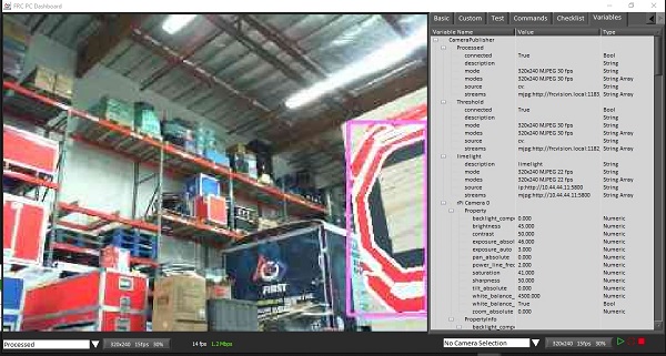
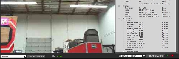
My color finding tool
Here is the desktop application that I used to find the biggest blob of red in the scene. Used this first to find the best values, then use these settings on the Raspberry Pi.
    #include "opencv2/core.hpp"
    #include "opencv2/imgproc.hpp"
    #include "opencv2/highgui.hpp"
    #include
    #include

    using namespace cv;
    using namespace std;
The global variables, I put these in global memory so they do not have to be reallocated and deallocated every loop.
    int mMorphSize = 7;
    vector > mContours;
    vector mHierarchy;
    Rect mRectangle;
    Mat mSourceImage;
Set the entry point of the program and allocated the values for thresholding the image.
    int main(int argc, char** argv)
    {
        int low1Value   =   0;
        int high1Value  =  39;
        int low2Value   =   0;
        int high2Value  =  32;
        int low3Value   =  40;
        int high3Value  = 130;
Open up the camera, read one frame and get the size of the frames.
        VideoCapture cap(1); //capture the video from web cam
        // Can't open the camera
        if (!cap.isOpened())  // if not success, exit program
        {
            cout << "Cannot open the web cam" << endl;
            return -1;
        }

        bool bSuccess = cap.read(mSourceImage); // read a new frame from video

        Size matSize;
        matSize.width = mSourceImage.cols;
        matSize.height = mSourceImage.rows;
Start the loop and read in a frame.
        // Idle loop
        while (true)
        {
            bool bSuccess = cap.read(mSourceImage); // read a new frame from video

            if (!bSuccess) //if not success, break loop
            {
                cout << "Cannot read a frame from video stream" << endl;
                break;
            }
Allocate the image to hold the thresholded image and a copy of that to be used later. Then threshold the image. Thresholding is a way to take a color image and return a black and white image. The three sets of values are used to ‘chop’ each channel into black and white and then combine all of these ‘chopped’ channels into one image.
            Mat imgThresholded;
            Mat imgThresholdedCopy;

            inRange(mSourceImage, Scalar(low1Value, low2Value, low3Value),
                Scalar(high1Value, high2Value, high3Value), imgThresholded); //Threshold the image
The morphing commands (erode, dilate) are used to remove all of the noise in an image. It also makes the colors in an image better connected.
            //morphological opening (remove small objects from the foreground)
            erode(imgThresholded, imgThresholded,
                getStructuringElement(MORPH_ELLIPSE, Size(mMorphSize, mMorphSize)));
            dilate(imgThresholded, imgThresholded,
                getStructuringElement(MORPH_ELLIPSE, Size(mMorphSize, mMorphSize)));

            //morphological closing (fill small holes in the foreground)
            dilate(imgThresholded, imgThresholded,
                getStructuringElement(MORPH_ELLIPSE, Size(mMorphSize, mMorphSize)));
            erode(imgThresholded, imgThresholded,
                getStructuringElement(MORPH_ELLIPSE, Size(mMorphSize, mMorphSize)));
Finding the contours is the process of taking the black and white image and find out all of the connected items, as well as the connected items inside other items. The function that finds the contours consumes the image, so the image is not usable after this process so we make a copy of it.
            // finding the contours corupts the image passed in
            imgThresholded.copyTo(imgThresholdedCopy);

            findContours(imgThresholdedCopy, mContours, mHierarchy,
                RETR_TREE, CHAIN_APPROX_SIMPLE, Point(0, 0));
Finding the largest contours by area.
            double largestArea = -1;
            int largestCont = -1;

            for (int i = 0; i < mContours.size(); i++)
            {
                double area = contourArea(mContours.at(i));

                if (area > largestArea)
                {
                    largestArea = area;
                    largestCont = i;
                }
            }
If there is a largest contour, put a white line around it, and then put a purple bounding box around the object.
            // Are there contours
            if (-1 != largestCont)
            {
                mRectangle = boundingRect(mContours.at(largestCont));
                approxPolyDP(Mat(mContours.at(largestCont)), mContours.at(largestCont), 3, true);

                Scalar color = Scalar(255, 255, 255);
                drawContours(mSourceImage, mContours, largestCont, color, 2, 8, mHierarchy, 0, Point());
                Scalar color2 = Scalar(255, 128, 255);
                rectangle(mSourceImage, mRectangle, color2, 2);
            }
Display the bounding box to the console.
            // Did we find the biggest contour, display it
            if (-1 != largestCont)
            {
                mRectangle = boundingRect(mContours.at(largestCont));
                approxPolyDP(Mat(mContours.at(largestCont)), mContours.at(largestCont), 3, true);
                printf("X:%4d Y:%4d W:%4d H:%4d A:%6.1f\n",
                    mRectangle.x, mRectangle.y, mRectangle.width, mRectangle.height, largestArea);
            }
Show the two images.
            // Show the images
            imshow("Thresholded Image", imgThresholded); //show the thresholded image
            imshow("Original", mSourceImage); //show the original image
The user can exit the program by the escape key.
            //wait for 'esc' key press for 30ms. If 'esc' key is pressed, break loop
            if (waitKey(30) == 27)
            {
                cout << "esc key is pressed by user" << endl;
                break;
            }
        }

        return 0;
    }
CPP Example on the Raspberry PI
In the example folder your will find the cpp example. In that folder there is a file called main.cpp, this is the server code for finding the image. In this file there is a lot of code that you should not touch. The piece of code that all your code should go into is:
    // example pipeline
    class MyPipeline : public frc::VisionPipeline {
      public:
        int val = 0;

        void Process(cv::Mat& mat) override {
          ++val;
        }
    };
The idea of this code is that the original image (mat) is taken in and the output should be network table entries to the roboRio.
The hello world program I use to make sure that the net tables is working is the sin wave, by the way, this code uses an older way of sending things through NetworkTables, so it will give warnings:
    class MyPipeline : public frc::VisionPipeline {
      public:
        double mVal = 0.0;
        nt::NetworkTableEntry mSin;

        MyPipeline()
        {
          wpi::outs() << "Building pipeline\n";
          auto inst = nt::NetworkTableInstance::GetDefault();
          mSin = inst.GetEntry("/sin");
        }

        void Process(cv::Mat& mat) override {
          mVal += 0.01;
          double sinValue = sin(mVal);
          nt::SetEntryValue("/sin", nt::Value::MakeDouble(sinValue));
        }
    };
Notice that you will need to add the constructor to the MyPipeline to set up the NetTable Entry.
The hello world program for image processing is putting a rectangle over the image. We don’t care where the rectangle is we just want to see is show up.
    class MyPipeline : public frc::VisionPipeline {
      public:
        cs::CvSource mOrigSource;

        MyPipeline()
        {
          wpi::outs() << "Building pipeline\n";
          mOrigSource = frc::CameraServer::GetInstance()->PutVideo("stream2", 320, 240);
        }

        void Process(cv::Mat& mat) override {
          cv::rectangle(mat, cv::Point(10, 10), cv::Point(100, 100), cv::Scalar(0, 255, 0),5);
          mOrigSource.PutFrame(mat);
        }
    };
What this does is open up another stream to the drivers station. This one is called stream2. If you run this program then on the default dash board, stream2 will show up on the camera drop down. In the constructor we setup the new stream as a CvSource. This also take in an image dimension. This dimension should be equal or smaller than the dimension found in the config file of /boot/frc.json.
Now that the rectangle test is working, I port my code from desktop computer to the Raspberry PI..
class MyPipeline : public frc::VisionPipeline {
public:
// The Nettable attributes
nt::NetworkTableEntry mX;
nt::NetworkTableEntry mY;
nt::NetworkTableEntry mArea;
nt::NetworkTableEntry mHigh;
nt::NetworkTableEntry mLow;
// The streams to send to the drivers station
cs::CvSource mThreshold;
cs::CvSource mOrigSource;
// The threasholding values
int mLow1Value = 0;
int mHigh1Value = 255;
int mLow2Value = 90;
int mHigh2Value = 226;
int mLow3Value = 214;
int mHigh3Value = 255;
int mMorphSize = 7;
std::vector > mContours;
std::vector
mHierarchy;
cv::Rect mRectangle;
MyPipeline()
{
wpi::outs() << "Building pipline\n";
auto inst = nt::NetworkTableInstance::GetDefault();
mX = inst.GetEntry("/rp/x");
mY = inst.GetEntry("/rp/y");
mArea = inst.GetEntry("/rp/area");
mHigh = inst.GetEntry("/rp/high");
mLow = inst.GetEntry("/rp/low");
mThreshold = frc::CameraServer::GetInstance()->PutVideo("Threshold", 320, 240);
mOrigSource = frc::CameraServer::GetInstance()->PutVideo("Processed", 320, 240);
}
void Process(cv::Mat& mat) override {
cv::Mat imgThresholded;
cv::Mat imgThresholdedCopy;
cv::Mat imageInHueSatVal;
// mHigh1Value = mHigh.GetDouble(255);
// mLow1Value = mLow.GetDouble(0);
// Convert the captured frame from BGR to HSV
// I like working in Hue Sat Value
cv::cvtColor(mat, imageInHueSatVal, cv::COLOR_BGR2HSV);
cv::inRange(imageInHueSatVal, Scalar(mLow1Value, mLow2Value, mLow3Value),
Scalar(mHigh1Value, mHigh2Value, mHigh3Value), imgThresholded); //Threshold the image
//morphological opening (remove small objects from the foreground)
cv::erode(imgThresholded, imgThresholded,
cv::getStructuringElement(cv::MORPH_ELLIPSE,
cv::Size(mMorphSize, mMorphSize)));
cv::dilate(imgThresholded, imgThresholded,
cv::getStructuringElement(cv::MORPH_ELLIPSE,
cv::Size(mMorphSize, mMorphSize)));
//morphological closing (fill small holes in the foreground)
cv::dilate(imgThresholded, imgThresholded,
cv::getStructuringElement(cv::MORPH_ELLIPSE,
cv::Size(mMorphSize, mMorphSize)));
cv::erode(imgThresholded, imgThresholded,
cv::getStructuringElement(cv::MORPH_ELLIPSE,
cv::Size(mMorphSize, mMorphSize)));
// finding the contours corrupts the image passed in
imgThresholded.copyTo(imgThresholdedCopy);
cv::findContours(imgThresholdedCopy, mContours, mHierarchy,
cv::RETR_TREE, cv::CHAIN_APPROX_SIMPLE, Point(0, 0));
double largestArea = -1;
int largestCont = -1;
for (int i = 0; i < mContours.size(); i++)
{
double area = contourArea(mContours.at(i));
if (area > largestArea)
{
largestArea = area;
largestCont = i;
}
}
// Are there contours
if (-1 != largestCont)
{
mRectangle = boundingRect(mContours.at(largestCont));
approxPolyDP(Mat(mContours.at(largestCont)),
mContours.at(largestCont), 3, true);
Scalar color = Scalar(255, 255, 255);
drawContours(mat, mContours, largestCont, color, 2, 8,
mHierarchy, 0, Point());
Scalar color2 = Scalar(255, 128, 255);
rectangle(mat, mRectangle, color2, 2);
}
// Did we find the biggest contour, display it
if (-1 != largestCont)
{
mRectangle = boundingRect(mContours.at(largestCont));
approxPolyDP(Mat(mContours.at(largestCont)),
mContours.at(largestCont), 3, true);
mX.SetValue(nt::Value::MakeDouble(mRectangle.x+(mRectangle.width/2)));
mY.SetValue(nt::Value::MakeDouble(mRectangle.y+(mRectangle.height/2)));
mArea.SetValue(nt::Value::MakeDouble(largestArea));
}
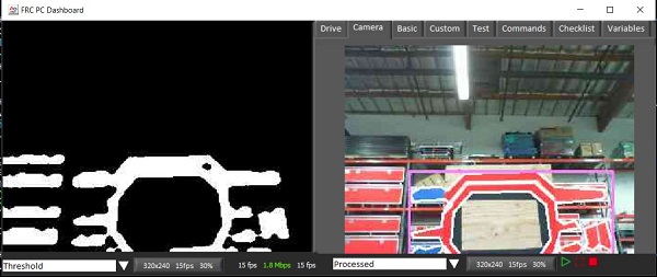
mThreshold.PutFrame(imgThresholded);
mOrigSource.PutFrame(mat);
}
};
This code sends back the biggest blob as three NetTable Entries, /rp/x, /rp/y, /rp/area. The x and y are the center of the blob.