CAD Models
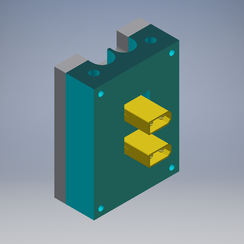
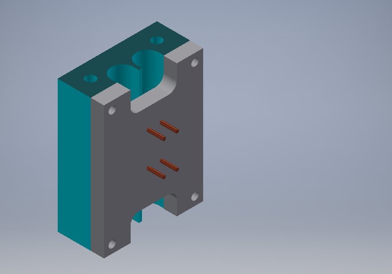
CAD Model Parts LibraryGear Boxes
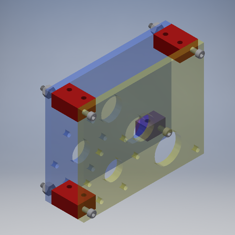
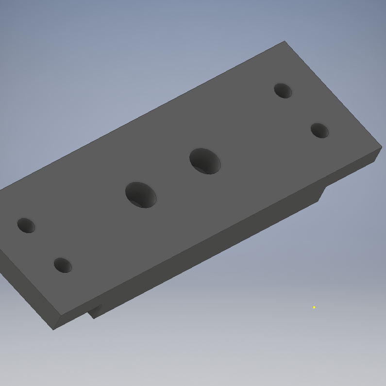
I’ve 3D printed these parts, I’m not sure if they will hold up over time. If you have the ability to machine these out of metal that would be better. If you are machining these, tap the top of all of the blocks. The 3D printed blocks are difficult to bolt the Top Plate to the gear boxes.
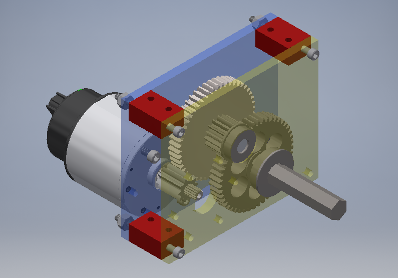
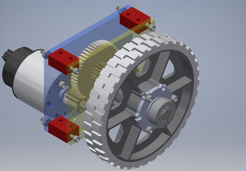
The output shaft needs to have 1.25 inches cut off of it to make it fit inside the robot, this is not necessary but the shafts will stick out a bit and catch of things. The gears inside the box are a kinda of tight fit. The normal E clip that goes onto the output shaft can’t be put in. If anyone has a good redesign of this part drop me a line.
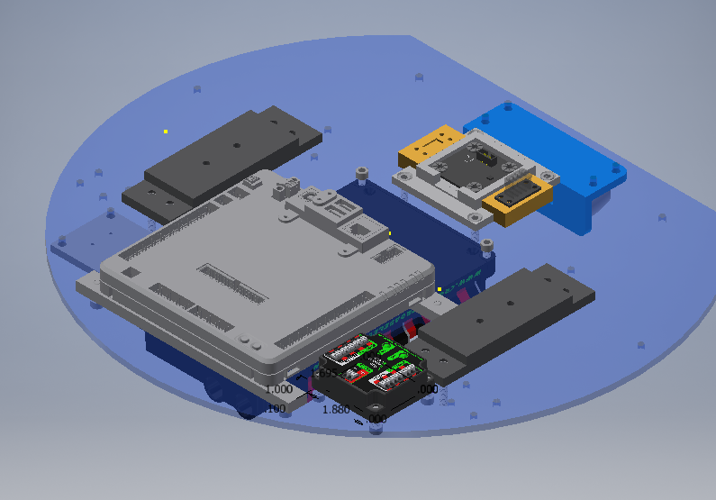
Bottom of the Robot
My power block did not quite work out the way I wanted. If I had to do it again, I would use the XT30 Extension cables from Rev Robotics and run both Ground Cables Up to the Power Distribution Board, and the Positive Cables down, around the batteries, to the main circuit breaker. Terminating both of these with ring crimps.
For the Jetson Nano’s plate, bolt it down using the screws at the front of the plate. This allows you to remove the Jetson without taking the robot a part.
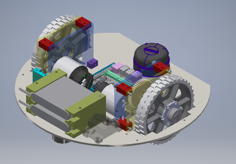
If you have machined the gear box blocks, I would keep them attached to the gear boxes. If you have 3D printed them, I would attach the top blocks to the Top Plate.
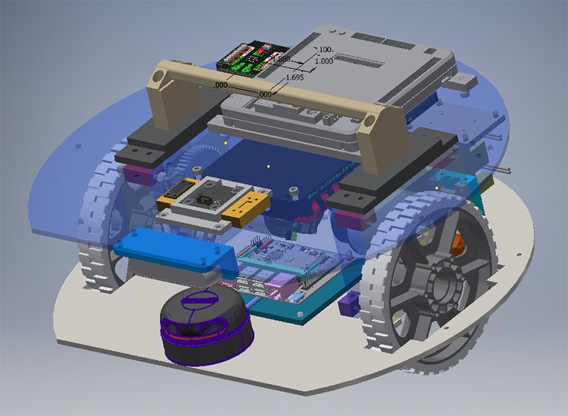
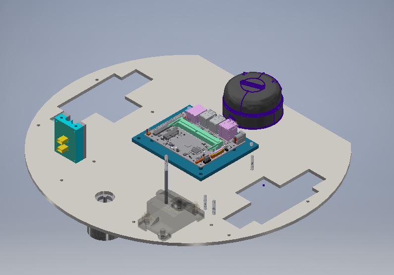
Top of the Robot
Press in two Hex nuts into the Handle Blocks, this allows the handle to be put on and taken off.
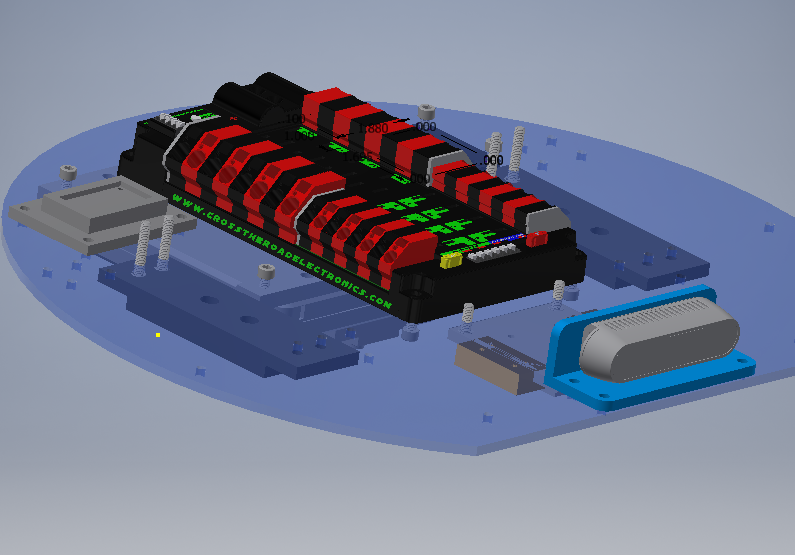
The 3D printed part in front of the PDP screw in the Pololu 5V step-down board.
A lot of wires need to be connected now.
Wire up the Rio and VRM like you would on an FRC robot. Then write up the radio (not pictured) like an FRC robot using the 12 inch ethernet cable. Connect the 18inch ethernet cable and run it through the hole next to the Rio, this will go to the Jetson Nano.
The motors will be powered by two 40amp breakers (you can probably go 30amps or even 20amps the motors should not draw much). The wire will go to the back of the robot, see below. The 5amp breaker will go to the Pidgeon on the top of the robot. The 10amp breaker will go to the 5V Pololu step-down. The other end of this step down will go into the barrel plug for the Jetson.
The CAN bus will go from the Rio, to Pidgeon, to Right motor, Left motor, and finally the PDP. There will need to be two CTR Can connectors. On from the Pidgeon to Right motor, and one between both motors.
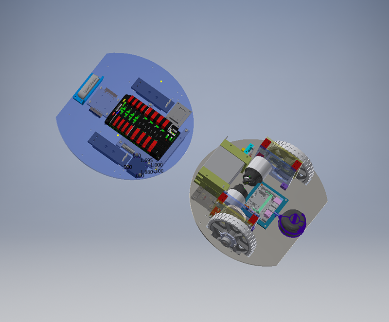
The robot should be wired up with the top and bottom next to each other. Then the top of the robot should be turned over and attached to the bottom.
Connecting the top to the bottom should be easy if the gear box blocks are tapped. Just run the screws through the handle blocks and into the gear box blocks.
If you have 3D Printed the blocks, it’s harder to connect. Take off the blocks and attach them to the top, then run the 2 inch bolts though the gear box plates and gear box blocks. This is tight. If it’s too tight to get these bolts in, remove the Slamtech Lidar, Jetson, Realsense camera, and the battery boxes, this will give you room to get the bolts in.